
Build It Right the First Time, Manufacturing Philosophy for Precision Fabrication
A frame that looks perfect in CAD and simulates beautifully is worth nothing if it can't be built accurately in a real shop by real people on a real timeline.
This is the gap between engineering school and engineering practice. In school, the output is a report. In practice, the output is a physical object that has to match the design closely enough to actually perform as predicted. Closing that gap requires thinking about manufacturing from the first day of design, not as an afterthought once the geometry is locked.
Here's how we approached it on the 2024 Bearcat Motorsports frame.
The Jig: Where Accuracy Actually Comes From
The welding jig is a fixture that holds all the tubes in their correct positions while they're being welded together. It's what determines whether the physical frame matches the CAD model, specifically, whether the suspension pickup points (the locations where the suspension attaches to the frame) end up where they're supposed to be.
This matters more than almost any other manufacturing detail. If a pickup point is off by a few millimeters, the suspension geometry is wrong, the car handles differently than it was designed to, and there's no way to tune your way out of it at the track.
The philosophy we used was to concentrate precision where it matters and accept larger tolerances where it doesn't. The suspension pickup points were located using machined aluminum blocks, milled to a known specification, positioned on the jig to a high standard of accuracy. Everything else, side tubes, impact structure, non-structural cross members, was located to a looser standard. The cockpit dimensionally matters the least. The suspension interfaces matter the most.
Allocating precision this way means you're spending machining time and attention where positional error has real performance consequences, not spreading it evenly across the whole structure.
The front and rear suspension interfaces were also welded as independent sub-assemblies before the full frame was joined. This isolates weld distortion locally. When you weld a continuous structure, heat from one joint can pull adjacent geometry out of position. Building front and rear independently and joining them last keeps any distortion contained.
The Laser Cutting Decision
Before 2024, tubes were cut and coped by hand, bandsaw, angle grinder, tube notcher. It's slow, it's inconsistent, and quality depends entirely on whoever is doing it at 11pm before a build deadline.
For 2024, we sent STEP files (a standard 3D model format) to a local metal fabrication shop. They returned precision laser-cut, fully-coped tubes in about a week for approximately $500 plus the cost of raw material we supplied.
The time savings were estimated at two weeks of build time. The accuracy improved significantly, laser-coped joints fit tightly and consistently, which means less filler material, cleaner welds, and better geometry. They also fit correctly the first time, eliminating the shop-floor problem-solving that eats hours and forces geometry compromises.
There's a cost-benefit calculation here that every fabrication project should make explicitly. $500 and one week of lead time versus two weeks of skilled labor and lower geometric accuracy is not a difficult comparison. Identify the steps in your process where outsourcing to a specialist produces better output at lower total cost, and make that call without sentimentality.
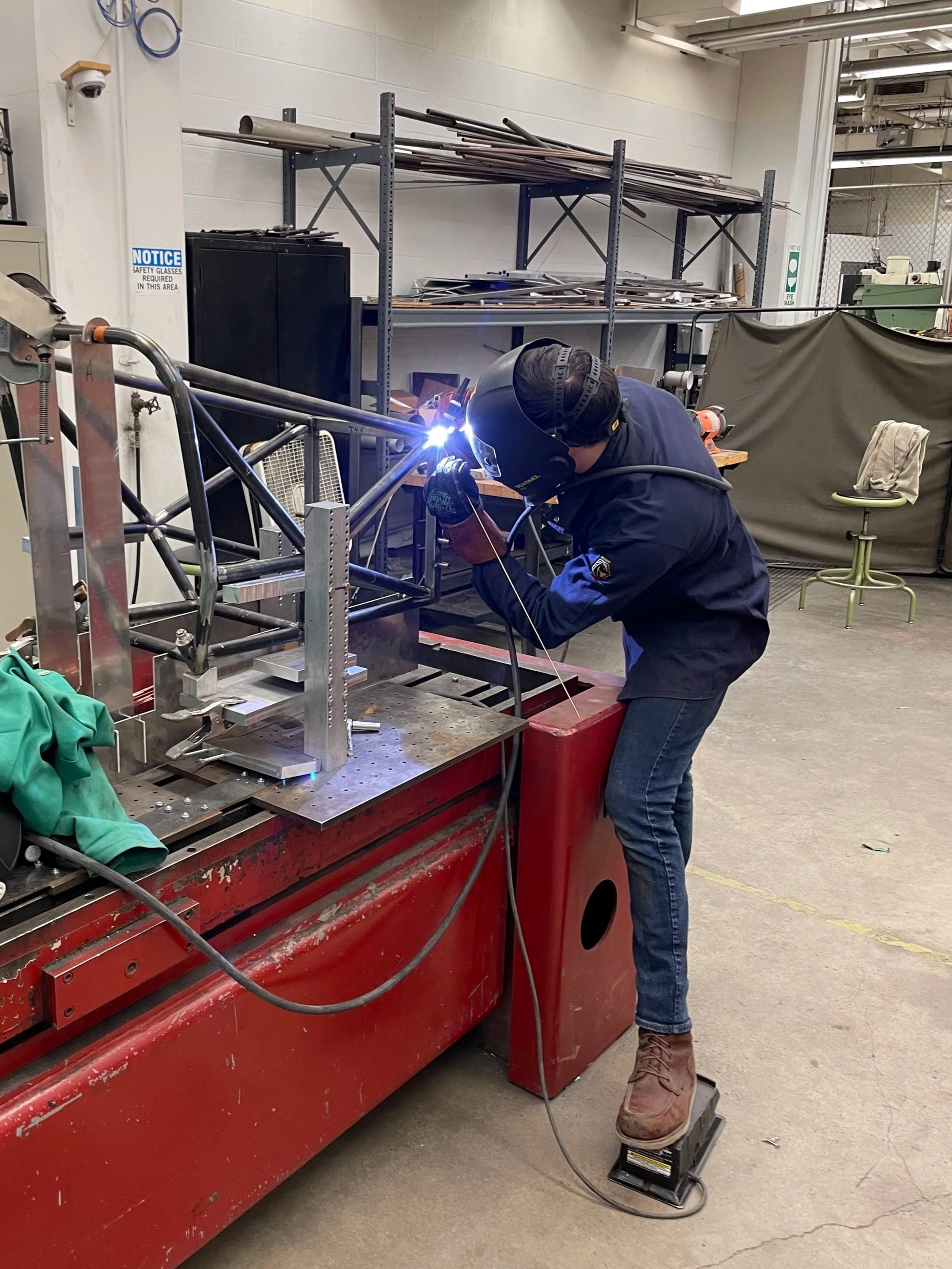
Welding: Heat Is the Enemy
About 75 hours of TIG welding went into the 2024 frame. The primary challenge in welding a steel space frame is heat warpage, steel contracts as it cools, and asymmetric heat input pulls joints out of position even after careful jigging.
Three mitigation strategies:
Tack first, weld second. Each section of the frame was tacked together, small, quick welds that hold position, before any full passes were run. Tacking establishes the geometry and gives the structure enough rigidity to resist distortion during full welding. Completing one joint at a time introduces new distortion into an increasingly rigid structure with every pass.
Weld opposing sides in sequence. Welding the top of a joint and letting it cool pulls the joint upward as the metal contracts. Alternating heat input around the joint, and across sides of the frame itself, can help neutralize this effect.
Stay in the jig as long as possible. The jig resists distortion mechanically. Every weld completed while the frame is still fixtured is a weld the jig is working against.
What This Means for Your Project
If you've ever had a prototype come back from a manufacturer and not fit the way the CAD said it should, the root cause is almost always one of two things: the wrong features were held to tight tolerance, or nothing was held to tight tolerance and the errors stacked up somewhere critical.
The fix isn't "tighter tolerances everywhere", that drives costs up without solving the actual problem. It's identifying which interfaces in your design are functionally critical, designing those features to be manufacturable at the required precision, and explicitly specifying what tolerance is acceptable at every other interface.
That conversation, which dimensions matter and why, is one of the most valuable things an engineer can bring to a hardware development project early. It's much cheaper to have it in CAD than to have it after the first batch of parts comes back wrong.