
The Part Nobody Designs For. Why Integration Is Where Hardware Gets Hard
Nobody talks about packaging in prototypes. It doesn't show up in the title of engineering papers. It doesn't get its own software. It's not what gets showcased in the design poster.
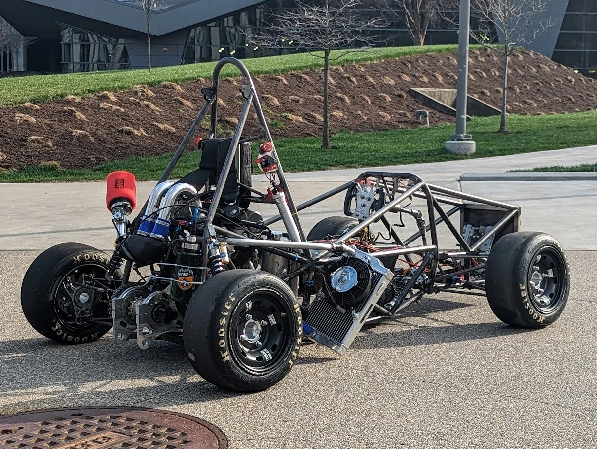
But in building the 2024 Bearcat Motorsports frame, packaging decisions, where things live in space relative to each other, produced more consequential engineering outcomes than almost anything else on the project. Get it right and the car is light, fast, and maintainable. Get it wrong and you're cutting and rewelding tabs two weeks before competition because a brake line doesn't clear a frame tube.
What Packaging Actually Means
Packaging is the discipline of spatial reasoning at the system level. It's not enough to design a frame that hits its stiffness target, or a suspension that hits its geometry goals, or an engine mount that passes structural analysis. Those components have to coexist in three-dimensional space, assembled in a sequence that's physically possible, and accessed for maintenance without removing six other things first.
On the 2024 car, two packaging decisions had direct performance implications and shaped the frame design significantly.
The 37° driver recline. Reclining the driver further back lowers the center of gravity of one of the heaviest things in the car. Lower center of gravity means the car can corner harder before the inside tire starts to lift. The tradeoff is volume: a more reclined driver takes up more horizontal space, which constrains where the firewall goes and how everything behind the driver gets packaged. Every dimension in that zone had to be worked out with the driver geometry present in the model, not added afterward as an afterthought.
Front suspension struts inside the cockpit. Moving the front struts inboard, inside the cockpit structure rather than outside it, reduced the car's yaw inertia. Yaw inertia is resistance to direction changes; rotating mass closer to the center of the car resists turning less. It also cleaned up airflow along the sides of the car, which the aerodynamics team cared about. The structural consequence was that the frame had to accommodate that geometry internally, imposing constraints on tube routing that didn't exist in prior designs.
Neither decision was made by the frame team alone. Both came from system-level conversations between the frame, suspension, aerodynamics, and driver ergonomics groups early in the design cycle, before geometry was locked.
The Complete Car Model
One of our explicit design goals was to validate access to every maintenance item in CAD before the build started, motor mount bolts, oil system access, electronics routing, all of it. This meant the master CAD assembly had to represent the complete car, not just the frame in isolation.
This is harder than it sounds. It requires every sub-team to produce CAD geometry on roughly the same schedule, a version control system that keeps the assembly current as things change, and the discipline to check clearances not just for installation but for tool access, not just for the static assembled state but for the maintenance state.
The payoff is that problems surface in CAD, where they cost nothing to fix, rather than in the shop, where they cost time, material, and morale.
Assembly Sequence Is a Design Input
A design that can't be assembled or maintained is a design that fails in the field. The order in which components go in and come out has to be thought through in the model before it becomes a shop problem.
If your fuel system can only be removed after pulling the engine, and the engine can only be removed after disconnecting the exhaust, and the exhaust requires removing the rear bodywork first, that sequence needs to be understood and accepted before any of it gets built. Finding it during a teardown at competition is finding it at the worst possible time.
What This Means for Your Project
Hardware product development consistently underestimates integration. Individual components get designed thoroughly. The system-level geometry gets figured out under pressure, late in the program, when parts are already manufactured and conflicts are expensive to resolve.
The symptom is usually a first prototype that works mechanically but has a cable that interferes with a cover, or a fastener that can't be reached once the assembly is complete, or a seal that can only be replaced by disassembling half the product. These aren't design failures in the traditional sense, the individual parts are often correct. They're integration failures.
The fix is a complete system layout in CAD as early as possible, even if many components are represented as rough placeholder geometry. Rough geometry in the right position catches interference problems. Detailed geometry that exists only in isolation catches nothing.
If your development process doesn't include an explicit integration review, where someone checks the whole assembly for clearances, assembly sequence, and maintenance access, that's worth adding before your next prototype build.